Around the end of 2019, I was given a 3D printer by a dear friend of mine.
But it wasn’t only until March when I realised lockdown was a real thing and all my outdoorsy hobbies like travelling, hiking, photography, or just wandering around, were no longer an option.
We’ve all been there.
No need to sweat this topic any further, I agree.
Anyway, by the end of March, I had to find something interesting to do and keep me busy whilst stuck at home. I had a job, and I was very lucky about that, but what about the free time I used to get out and do things outside. I was still stuck at home. It’s been then that I pulled that 3D Printer from the corner where it’s been sitting doing nothing, and started fiddling and playing around with it. Getting into 3D printing to me was more about learning the technology than actually print something useful, so I decided to dismantle the printer, learn how things worked mechanically and electronically. I rebuild the printer changing every board entirely, converted it to 32Bit and added a few features along the way (a new post will come soon about this).
That process got me interested in the Arduino platform and the world of sensors, circuits and microcontrollers.
I then randomly bumped into some article about VFD displays, the ones you’d seen if you had any single electronics device back in the 90’s (which we all did, did you not have a VCR?! :D) .. and finally I’ve read some blog about the”the Nixie clocks”.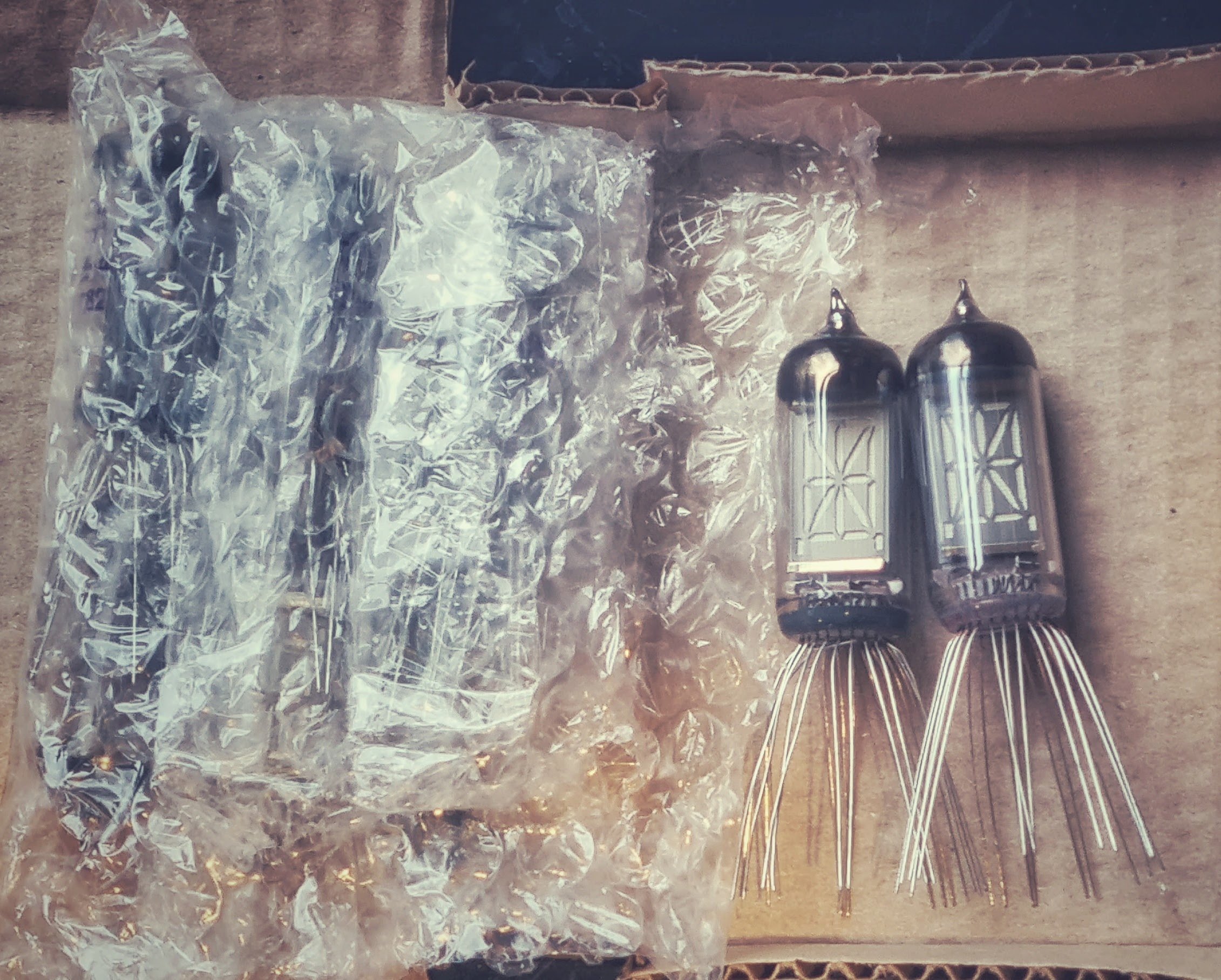
Nixies tubes are driven by high voltage (around 180V) and I didn’t feel like I had the knowledge to start exploring that area, but the VFD, on the other hand, work with relatively low voltages, from 1.5V for the filament and to around 40V for the grids… and I got hooked straight away.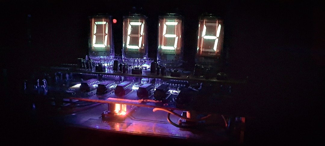
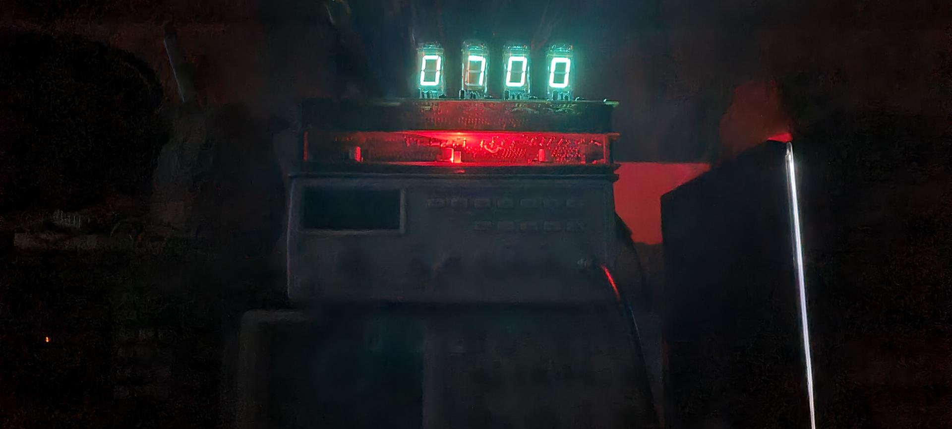
My first clock was driven by an Arduino Nano and had a few sensors, a real time clock, and a bunch of lines of code to put on it to get it started:
After a couple of months fiddling with Arduino and the VFD tubes I decided I wanted to step back and learn what actually drives computers and all the devices I’ve been using for almost 40 years! The mighty transistors!
I rolledup for a 140Hours online course in Electronics and Engineering and started playing with Integrated Circuits, Logic gates and that was the beginning of a new journey I now call a hobby.
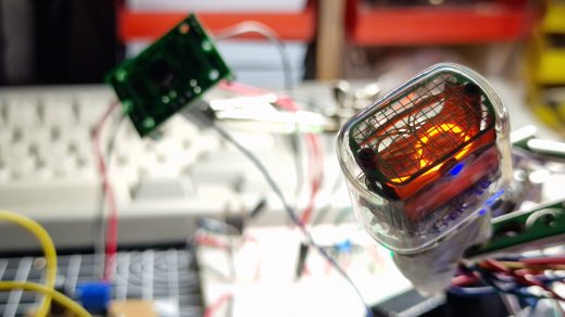
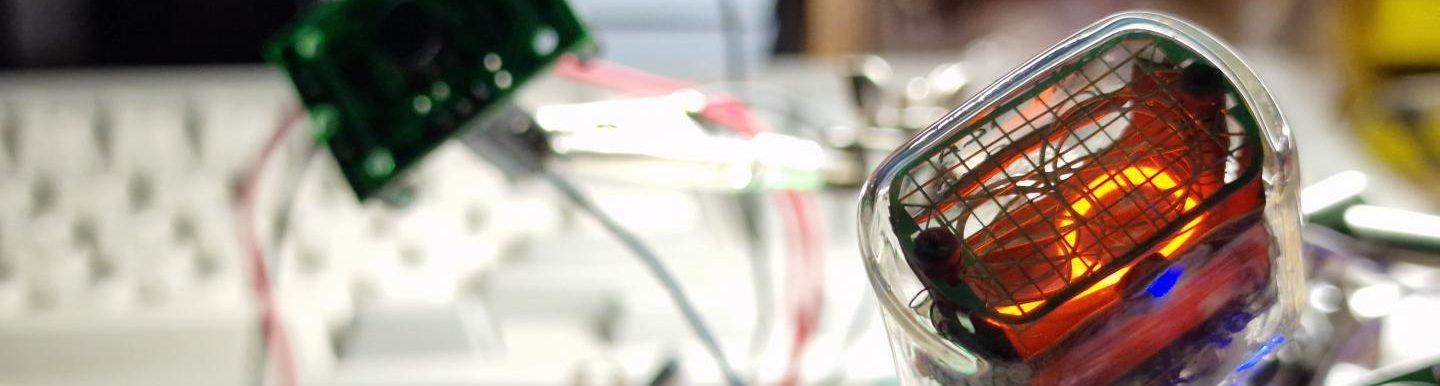
My first attempts had to start from the basics, driving simple LED with shift registers, decade counters and then drive the VFD lamps.
Here’s a first prototype:
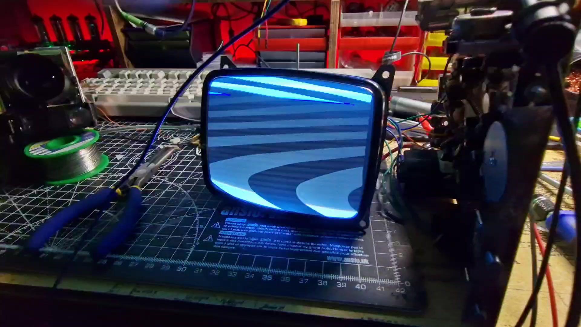
After a few weeks I had a finished prototype on Breadboards: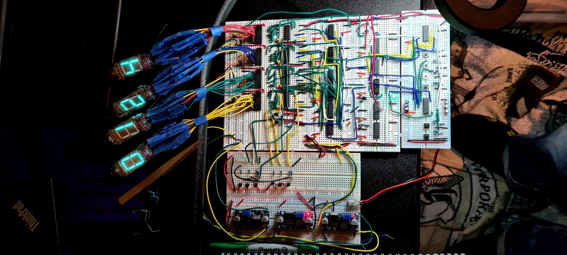
That was pretty exciting!
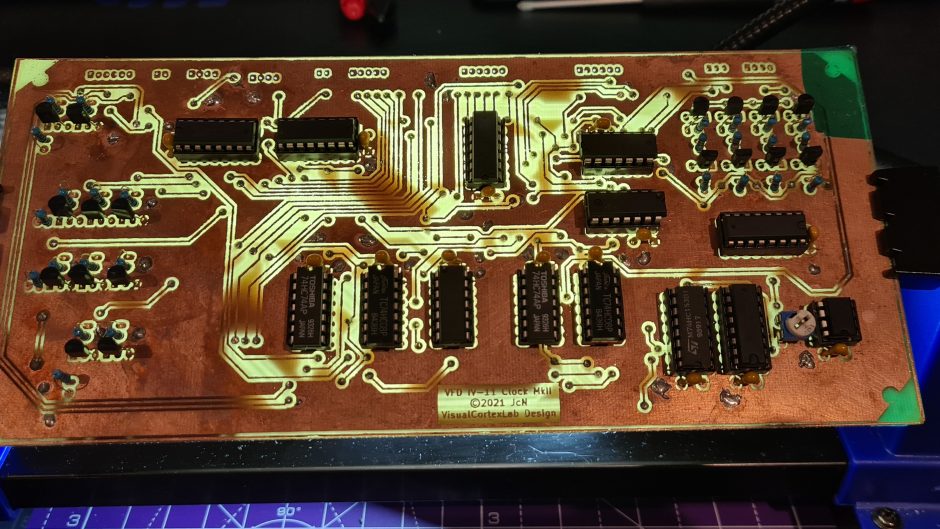
I finally had to understand how to put all those components on a PCB, and I was certain that I wouldn’t have had the PCB printed somewhere and posted at home, I would have etched them myself!
Etching PCB (more on this in a separate post) is a very cool process, frustrating at times (often), but it brought me back to when I was spending hours in my bathroom developing my 6×6!
I’ve used Kicad for the schematics: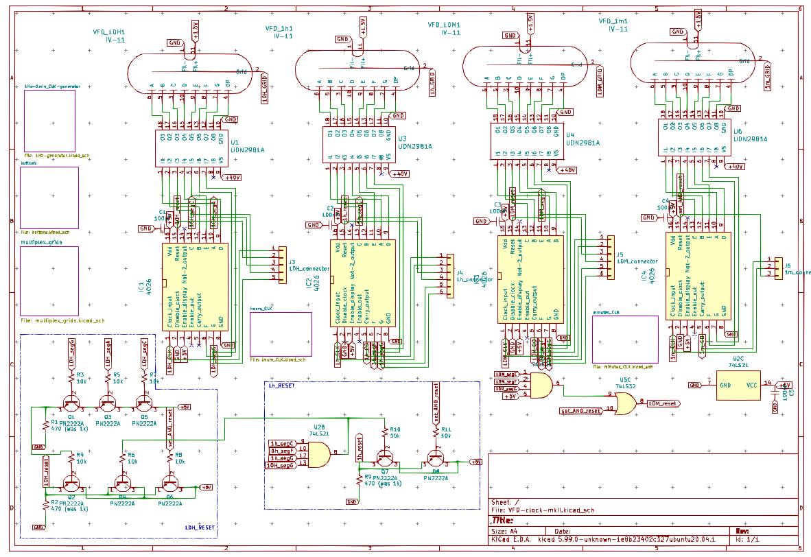
and the PCB design, it even does a quick 3D render of the PCB: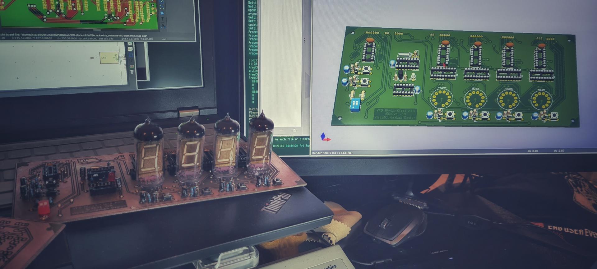
To learn the design and etching of the first PCB I replicated the part of the circuit that was generating the pulse for the VFD strobe effect, driven by a 555 time and a few transistors: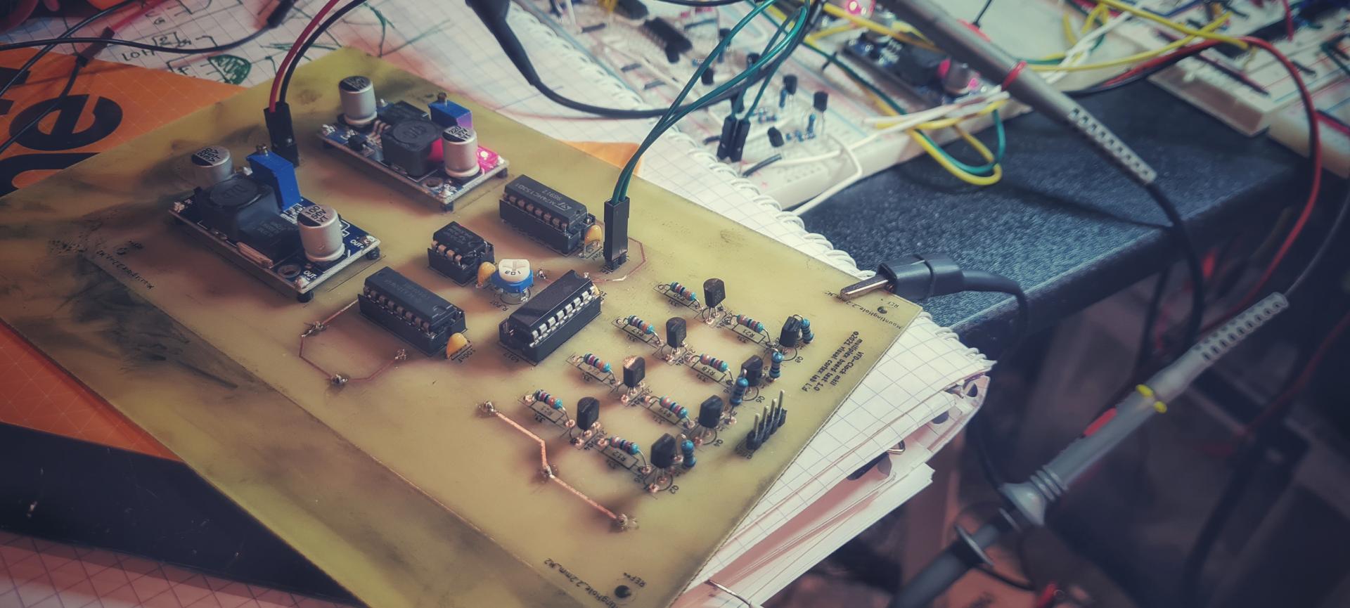 I’m already thinking about the next clock, and I decided to go back and improve every aspect of it, learning more in detail how to approach various part of the design.
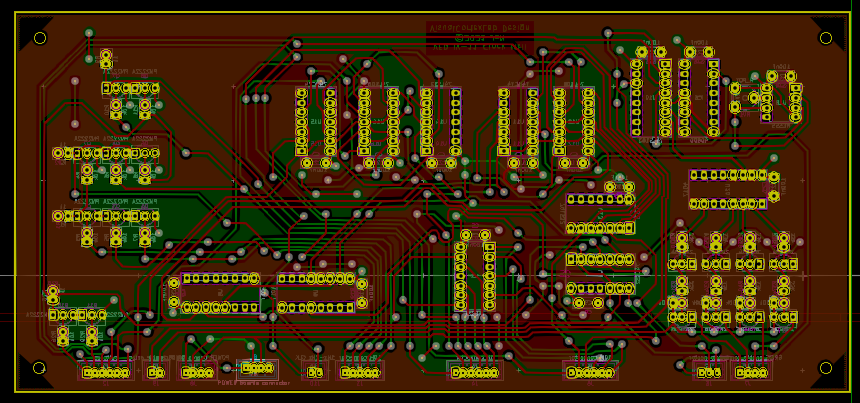
[to be continued….]
Right now I’m designing the AC filament driver supply voltage… back to the basics of inductors!
Stay tuned!